
I have a number of RFµ-328 boards from Ciseco that I am intending to use for a number of projects and I needed a way to program them without having to solder on the connectors. This is a simple little project to build a programmer for the devices as well as a first attempt at using pogo pins.
Parts needed
1 x RFu developer board, includes 0.1µF capacitor and 6 pin male FTDI connector
LED
470Ω resister (actually you can get use a lot lower value, this is just what I had to hand)
Connecting wire
Build
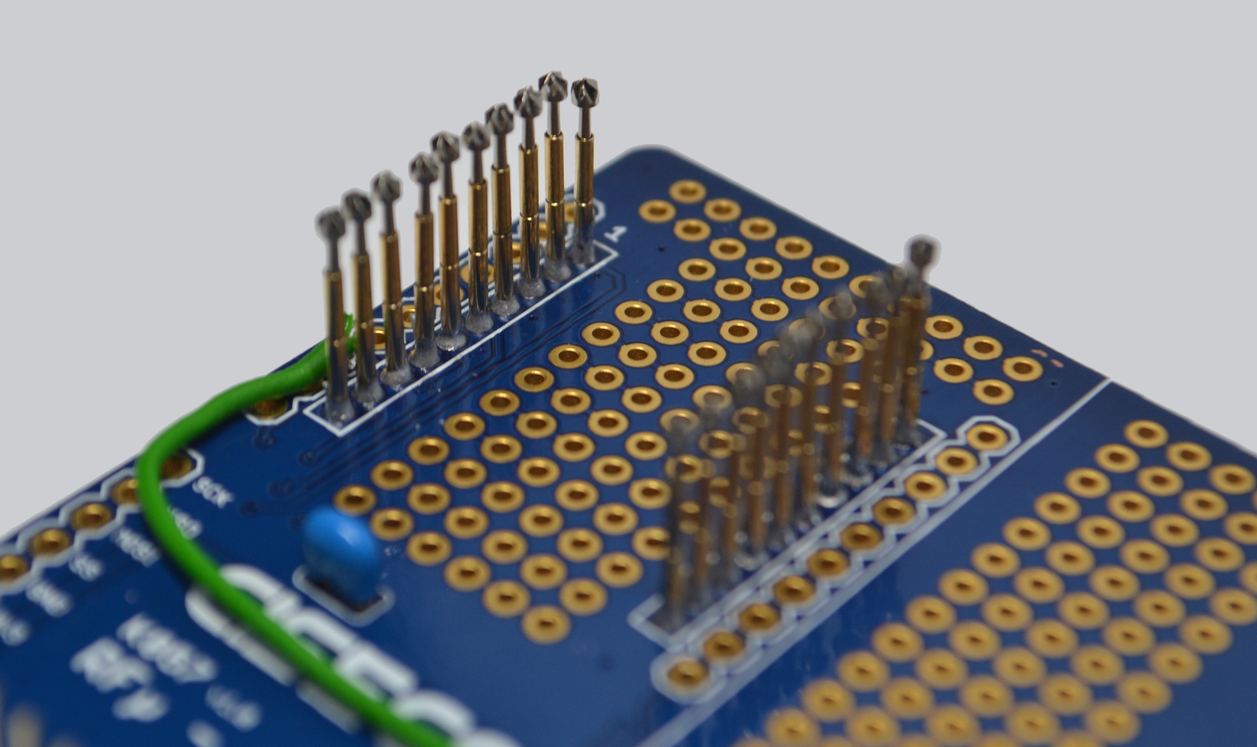
This first task is to make the holes of the two 10 way 2 mm sockets big enough to fit the pogo pins. I did this with a 1 mm drill bit and a hand drill due to the small size of the drill bit. Ideally you would do this with a pillar drill to make sure all the pins are perfectly vertical (mine are not). You also need to be careful not to rip off the pads.
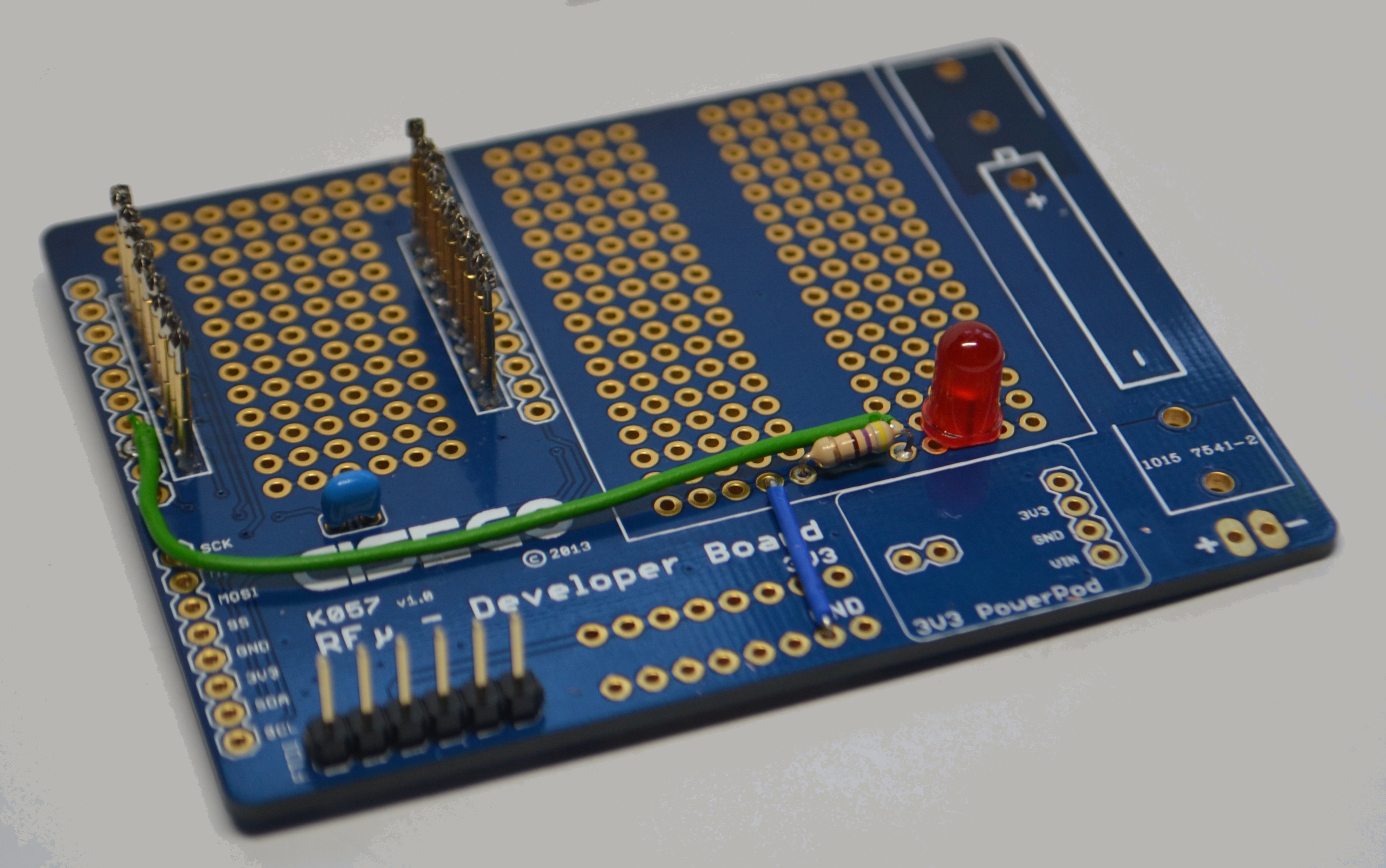
When all the holes have been widened we can start soldering components. Starting with the LED wires. You will need one long wire from pin 8 (Arduino pin 13) on the RFµ-328 breakout area to the prototype area and a short link from the prototype area to ground.

Then the resister, capacitor, LED and 6pin male header can be soldered on.
Finally the pogo pins can be installed. I made pin 1 (Vdd) slightly lower than all the rest so that the power is the last thing to be connected, hopefully allowing the boards to be 'hot swapped'. Make sure you solder both the top and the bottom of the PCB as the plating will have been stripped away when enlarging the hole, plus to preserve as much of the copper the hole only just fits the pin so the solder will not flow through the hole.

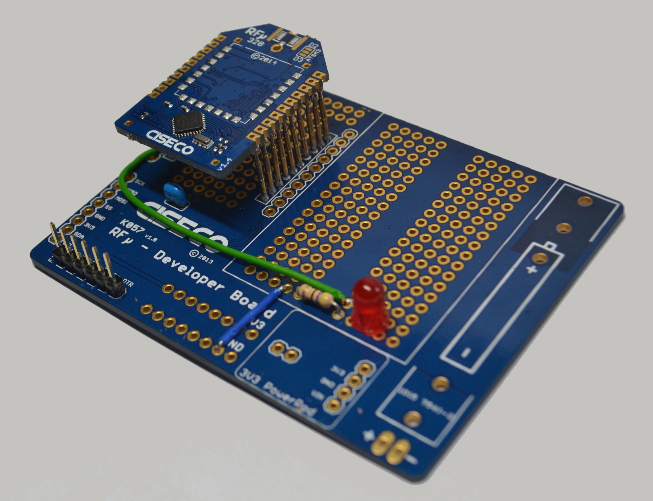
You should then have something like this;

Time to test
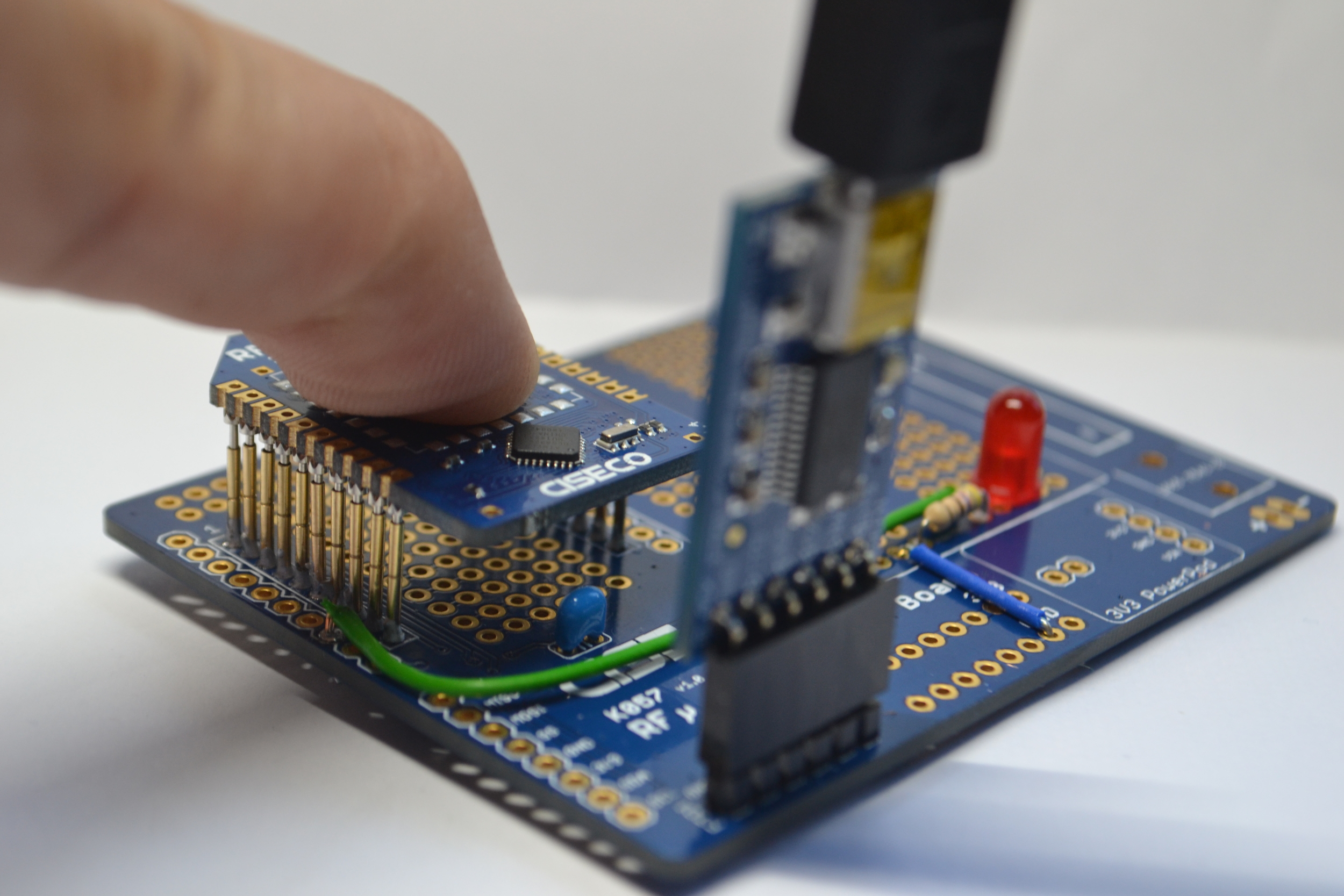
After doing some continuity tests, checking that all the pins are connected to what they should be and there are no shorts, we can connect up our FTDI cable.
Next load up Arduino IDE and the Blink example. We have our LED connected up to pin 13 so no changes are needed.
Place an RFµ-328 on the pogo pins and push down, then click the upload button in Arduino IDE.

If all goes well you should end up with a flashing LED;
Todo
There are still a few bits I would like to do on the programmer. First would be to mount the programmer on a board with some feet and second is to use a flip down Toggle Clamp to hold the RFµ-328 in place while programming/testing.